

Are you sure. This action can not be undone.
Semiconductors
The history of the transistor is a fascinating saga spanning decades of scientific effort and technological advances. It all began in 1926 when Julius Edgar Lilienfeld, an Austro-Hungarian-American physicist, patented a device that would lay the foundation for what would later be known as the transistor. Lilienfeld envisioned a field effect device with a metal electrode separated from a semiconductor by a thin oxide layer.
However, despite his pioneering vision, the technological limitations of the time prevented the practical realization of his invention. The idea was forgotten for decades.
It was not until the 1940s that advances in the understanding of semiconductors and the growing need for switching and amplification devices in electronics led to renewed interest in solid-state device research.
In 1947, at Bell Laboratories, located in the United States, the breakthrough occurred. John Bardeen, Walter Brattain and William Shockley, working as a team, developed the first functional bipolar transistor. This device consisted of a germanium semiconductor with electrodes connected to each end. Using base currents, they managed to control the flow of current between the emitter and the collector, which allowed electrical signals to be amplified. This milestone marked the beginning of the transistor era.
The invention of the bipolar transistor also called BJT "Bipolar Junction Transistor" revolutionized the electronics industry, providing a more efficient and compact replacement for the vacuum tubes used until then. From portable radios to computers, transistors became the fundamental building blocks of modern electronics.
However, the search for more efficient and versatile devices continued. In the 1950s, Mohamed Atalla and Dawon Kahng, working at Bell Labs, developed the metal-oxide-semiconductor field-effect transistor (MOSFET transistor), which was based on Lilienfeld's initial concept. This device featured a simpler structure and offered better switching characteristics and energy efficiency.
The MOSFET, patented in 1959, became the cornerstone of the semiconductor industry, driving advances in consumer electronics, telecommunications and computing. Its refined design and ability to integrate into integrated circuits made it the centerpiece of the digital revolution.
From its modest beginnings in the 1920s to its evolution into the MOSFET transistor, the history of the transistor is a testament to the power of scientific research and technological innovation to transform the world and not stop. In the 1980s the IGBT transistor was invented. This transistor is considered a hybrid between the bipolar transistor and the MOSFET. In this case we have preferred to place the IGBT transistors outside of this section and they have their own section.
The main differences between the four types of transistors are:
Bipolar transistors, FETs, MOSFETs and IGBTs have been fundamental to the development of modern electronics. They are used in a wide range of devices, from radios to mobile phones.
All four types of transistors have undergone significant evolution since their invention. The main improvements have focused on:
The explanation of the operation of a bipolar transistor is very extensive. The following lines express in a very, very abbreviated way this operation.
Firstly, it is necessary to introduce some physical concepts of the transistor and to do so we will briefly comment on its semiconductor structure.
The bipolar transistor consists of a device composed of three semiconductor regions that are separated by PN junctions. In the figure immediately below, and on the left, a representation useful for analyzing the bipolar transistor is shown. It is essential that the doping of the regions be alternated; That is, if the emitter is P-type, then the base will be N-type and the collector will be P-type, resulting in a PNP-type bipolar transistor. On the other hand, if the emitter is type N, then the base will be type P and the collector will be type N, creating an NPN type bipolar transistor.
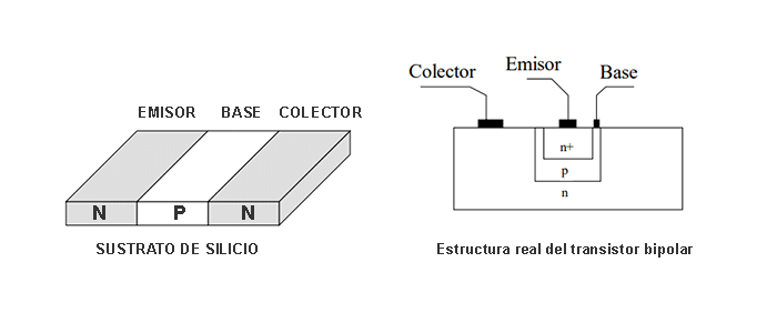
The manufacturing of the transistor is carried out on a silicon substrate, in which impurities diffuse to obtain the three regions mentioned above. The figure above and to the right shows the typical appearance of a real bipolar transistor found in any integrated circuit. On an n-type base (acting as a collector), p and n+ regions are diffused, in which the emitter and base contacts are placed.
The emitter must be highly doped (denoted p+). The higher the doping of the emitter, the more charge carriers it can contribute to the current.
The base must be narrow and lightly doped to minimize recombination in it, allowing most of the emitter current to pass to the collector, as will be seen later. If the base is not narrow enough, the device may not function as a transistor and behave more like two diodes in opposition.
The collector must be a less doped region than the emitter, and its characteristics are related to the recombination of the carriers coming from the emitter.
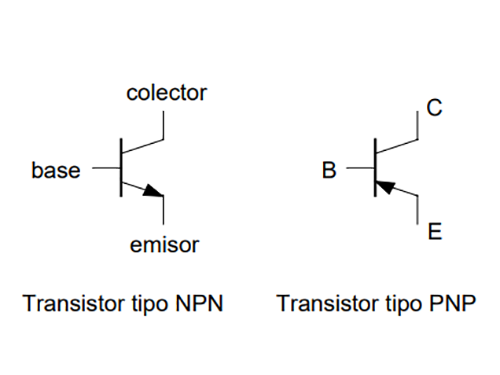
As we have seen previously, the bipolar transistor consists of three terminals: the emitter, the collector and the base. According to its construction, it can be classified into two types: NPN and PNP. The lower one shows the circuit symbols and the nomenclature of their terminals. To distinguish between an NPN and a PNP transistor, look at the direction of the arrow on the emitter terminal: on an NPN, the arrow points away from the transistor, while on a PNP, the arrow points inward. Furthermore, under normal operating conditions, the arrow indicates the direction of the current flowing through the emitter of the transistor.
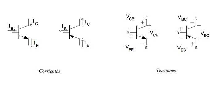
Typically, certain voltages and currents are set across the transistor, as illustrated in the two figures below. These definitions are the ones that will be used in these lines and follow a physical representation of them, since under normal operating conditions all defined currents and voltages are positive. Although there are other ways to indicate these voltages and currents, they will not be discussed in this section.
The operating zones of a bipolar transistor are closely related to its polarization. Biasing a transistor refers to the application of voltages or currents to its terminals to establish desired operating conditions. Depending on how the transistor is biased, it can operate in different regions that determine its behavior and output characteristics. The main areas of operation are:
These operating zones are closely related to transistor biasing, which can be achieved through specific circuit configurations. For example, in a voltage divider bias, resistors are used to apply specific voltages to the base and emitter, which places the transistor in the active region. In practice, biasing circuits are designed to ensure that the transistor operates as desired, either as a linear amplifier in the active region or as a switch in the saturation region, depending on the specific application.
Transistor polarization consists of setting its working point within a working zone in the absence of an input signal. We call this working area Q point. Typically this point is located in the active region of the transistor, which is where signals can be amplified in a linear and stable manner. However, it is possible for the Q point to be in the cutoff and saturation zones under specific circumstances, although this is not desirable in most applications.
The Q point is set by the voltages and currents at the terminals of the transistor when it is biased in a specific circuit. Biasing refers to the application of voltages or currents to the transistor terminals to establish its desired operating point.
In a bipolar transistor, biasing is achieved by circuits specifically designed to set the Q point at an optimal level. This ensures that the transistor operates stably and linearly in the active region, where it can amplify the input signal effectively.
Choosing the appropriate bias depends on several factors, such as the desired linearity, thermal stability, and amplifier efficiency requirements. Biasing circuits, such as voltage divider biasing or common emitter biasing, are designed to set the Q point optimally, taking into account the transistor specifications and circuit needs.
Temperature also influences the Q point and therefore the performance of the transistor. As the temperature changes, the electrical characteristics of the transistor, such as current gain β and reverse saturation current IS, may vary.
These changes in the characteristics of the transistor can affect the Q point and therefore the behavior of the circuit in which it is integrated. For example, an increase in temperature can cause the reverse saturation current to increase, which can shift the Q point and affect circuit stability.
To compensate for the effects of temperature, thermal compensation techniques are often used in circuit design. This may involve using components with complementary temperature coefficients or designing circuits that minimize the effects of temperature variation at the Q point.
In summary, the Q point is closely related to the transistor bias and temperature. Establishing a proper Q point is essential to ensure optimal and stable transistor operation in an electronic circuit, especially under varying temperature conditions.
The operation of the bipolar transistor can be explained using the Ebers-Moll equation, which describes the charge carrier currents (electrons and holes) in a bipolar transistor. The Ebers-Moll equation is a simplified description of transistor behavior and is based on the theory of charge transport in semiconductors.
The Ebers-Moll equation for an NPN type bipolar transistor is:
| Ic=IS * (eVBE/VT -1) - αR IS * (eVBC/VT -1) |
| IE = ßF IC + ßR IB |
Where:
| Ic | is the collector current |
| IE | is the emitter current |
| IB | is the base current |
| VBE | is the voltage between the base and the emitter |
| VBC | is the voltage between the base and the collector |
| IS | is the reverse saturation current of the emitter |
| VT | is the thermal voltage |
| βF y βR | they are the forward and reverse current gains, respectively |
| αR | is the reverse current gain |
The thermal voltage VT would be defined by K*T/q; where K is the Boltzmann constant, T is the temperature in degrees Kelvin and q is the charge of the electron. Therefore, it is a constant related to the absolute temperature of the semiconductor and the charge of the electron. Its value is typically around 25 or 26mV at room temperature (approximately 300º Kelvin. It is also known as the base-emitter junction voltage in bipolar transistors.
The thermal voltage is essential to describe the behavior of the transistor. It is a quantity essentially related to the thermal energy of the charge carriers (electrons and holes) in the semiconductor. The higher the temperature, the greater the thermal energy of the charge carriers and therefore the greater the thermal voltage.
In the Ebers-Moll equation, the thermal voltage term, VT, appears in the exponent of the exponential function that describes the relationship between the voltage VBE and the collector current Ic. This term reflects how the flow of charge carriers between the base and the emitter varies with temperature. In summary, thermal voltage defines the sensitivity of the transistor to changes in temperature and directly affects its behavior and operating characteristics.
At room temperature, the Ebers-Moll equation can be simplified by several approximations. The most common is the assumption that the exponential term eVBC/VT is approximately equal to e0 because VBE is relatively small compared to VT. This is valid in most typical cases of operation of a bipolar transistor at room temperature.
Therefore, at room temperature, the Ebers-Moll equation can be simplified as follows:
Ic∼IS (e0 -1) - αR IS * (eVBC/VT -1)
Ic∼ - αR IS * (eVBC/VT -1)
This simplification is commonly used in circuit analysis and design of bipolar transistors at room temperature, where VBE is much smaller than VT. However, it is important to remember that this simplification is an approximation and may not be valid in all cases, especially in applications where high precision is required.
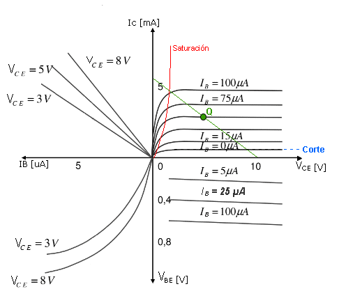
The graph of a bipolar transistor is shown in the image below.
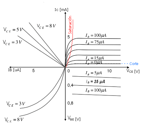
The collector current depends on the base current, which in turn depends on the base-emitter voltage. We have two border areas. On the one hand, in the lower area and with blue lines we have marked the cut-off area, where the collector current takes a very small value, close to ICO. Once the threshold voltage is exceeded, the base current grows exponentially with the bae-emitter voltage, obtaining high values in the collector current, until saturation of the transistor is reached. This threshold voltage in a silicon transistor is of the order of 0.5V. From 0.7V we would already be in the active zone, but reaching around 0.8V we would already be in saturation.
As we previously said point Q, we have to place it within the active zone in the absence of signal. In the figure below we have the same previous curve, where we already have the work point (Q) represented. The green line represents the loading line. which depends on the polarization of the transistor (in the absence of signal). If Q is very close to the ordinate axis, it means that it is close to the saturation region, while if Q is very close to the abscissa axis, it means that it is close to the cutoff region. Depending on the base current, the transistor is at one operating point or another, along the load line.
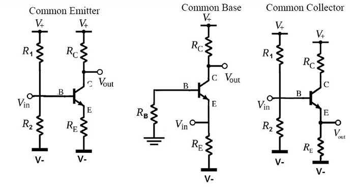
There are three basic configurations of a bipolar transistor used to amplify a signal and they are named based on how the terminals of the transistor (emitter, base and collector) are connected with respect to the signal source and the load. The three assemblies are shown in the figure below:
We are going to explore the analysis of a three-terminal component that shares many applications with the BJT or bipolar transistor, which we have already studied. Field effect devices are commonly known as FET (Field Effect Transistor) and there are two main types:
We will begin our study of these transistors by comparing some of their similarities and differences to BJTs. The main distinction between the two is that the BJT is current controlled, while the FET is voltage controlled. In both cases, the current in the output circuit is regulated by a parameter of the input circuit, either the current level or the applied voltage level.
FETs generate an electric field that modulates the conductivity of the output path without requiring physical contact between the controlled current and the control voltage. Similar to BJTs that are classified into npn and pnp types, FETs are distinguished by being n-channel or p-channel.
A key difference between these types of transistors is that while BJTs are bipolar, involving the participation of both types of carriers (electrons and holes) in the current, FETs are unipolar, depending only on one type of carrier: electrons for those of channel n and holes for channel p.
An essential feature of FETs is their high input impedance, which can reach several hundred megohms, much higher than that of BJTs, which typically have input impedances in the kiloohm range. This makes FETs ideal for amplifier applications.
However, BJTs are more sensitive to changes in the applied signal, which means that for the same variation in applied voltage, the corresponding variation in output current is greater in BJTs than in FETs. This results in generally higher AC voltage gains in amplifiers with BJTs than with FETs.
In general, FETs are more thermally stable and typically more compact than BJTs, making them especially useful in integrated circuits, especially MOSFETs.
A notable aspect of FETs is their ability to behave like resistors or capacitors, which allows the creation of circuits using exclusively FET transistors.
In the context of bipolar transistors (BJTs), we have observed that the current flowing from the collector to the emitter is directly proportional to the current flowing from the base, allowing the BJT to regulate the current. BJTs can handle a large amount of output current with a small input current at the base. On the other hand, in the case of junction field effect transistors (JFETs), the current flowing from the drain to the source is determined by the voltage applied to its gate. Therefore, it is a device that is controlled by voltage.
The JFET is more efficient than the BJT and can perform all the functions that a BJT can perform. It is widely used in the manufacturing of digital CMOS chips due to its efficiency, speed, low cost and compact size.
The illustration below represents an N-channel JFET transistor, with three terminals shown: drain, source, and gate. The drain and source are connected to the ends of the n-type semiconductor block, allowing current to flow from the drain to the source. In this case the two gate terminals are joined by a thin dotted line, which means that generally these devices have these two gate terminals joined together, but in some cases the two gate terminals are accessible independently. To regulate this current, two p-type regions are created near the n-type channel at both ends, which are connected internally to form the gate terminal of the JFET. These regions form two p-n junctions, generating a small depletion region. By biasing these junctions, we can control the width of the depletion region and therefore the amount of current flowing from the drain to the source. This same structure is inverted in the P-channel JFET.
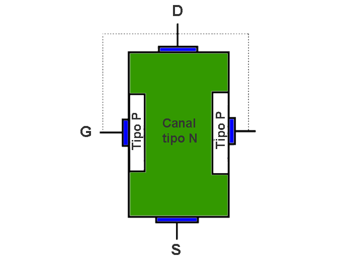 |
D (Drain). It is the terminal through which the carriers of the device (the electrons in the n-channel JFET and the holes in the p-channel JFET) S (Source). It is the terminal through which the carriers enter. G (Gate). It is the terminal through which the current of carriers through the channel is controlled. |
Let's consider that for the N-channel JFET above we connect the drain and source to a voltage supply (VDS) and short the gate to the source as shown. A current begins to flow from the drain to the source (drain current). By applying a voltage to the gate and the source we can control this current.
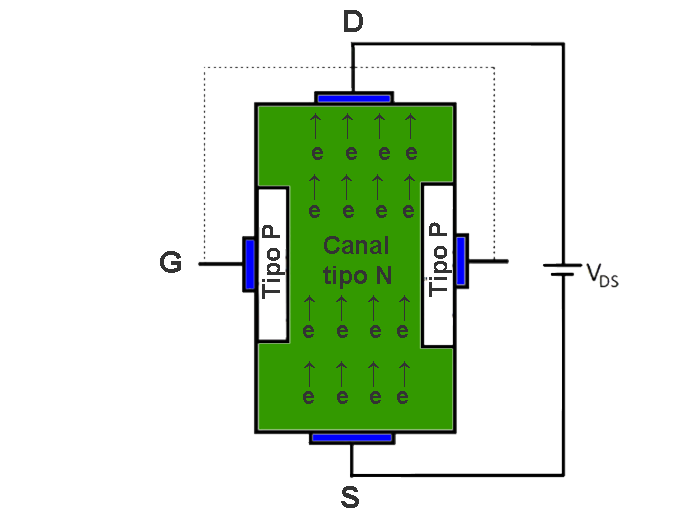
If we increase the drain-to-source voltage even further, the pn junctions will experience greater reverse bias and the depletion region will expand, as shown in the image below. Consequently, the resistivity of the channel will also increase. Therefore, the drain current will not continue to increase linearly.
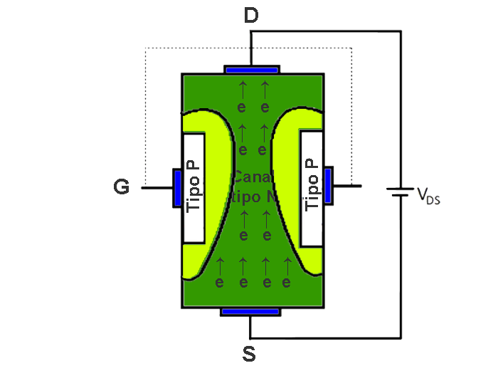
We can see that the depletion region is wider on the drain side and narrower on the source side. This occurs due to the resistivity of channel block n. When a power source is connected to the n-type block, drain current begins to flow, creating a voltage drop across it. The higher the resistance, the greater the voltage drop. Consequently, the drain side becomes more positively charged compared to the source side. As a result, junction polarization becomes more significant on the drain side.
If we continue to increase the voltage across the drain and source of the JFET, there will be a point where both depletion regions will touch each other. This condition is known as a pinch condition. The voltage between drain and source (VDS) at this point is known as pinch-off voltage (VP). At this stage, there will be no current flow from the drain to the source.
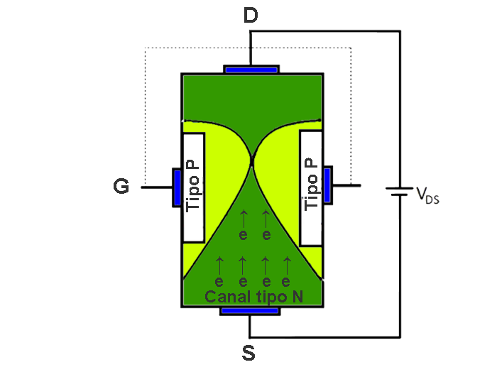
If there is no flow of any current through the channel. There will not any different voltage level across the channel. So depletion region will reshape itself and its width will be equal all around the junctions. Then channel will open again. This will allow drain current to flow again.
As we considered previously that there will not flow any drain current after pinch-off that was not right. Rather this is the maximum current (saturation region) which can flow from drain to source. If we increase the VDS even further the current will still constant. This is the maximum current at VGS =0 and VDS > VP and it is known as drain to source saturation (IDSS) current. In the case of P-channel JFET these consideration are reversed.
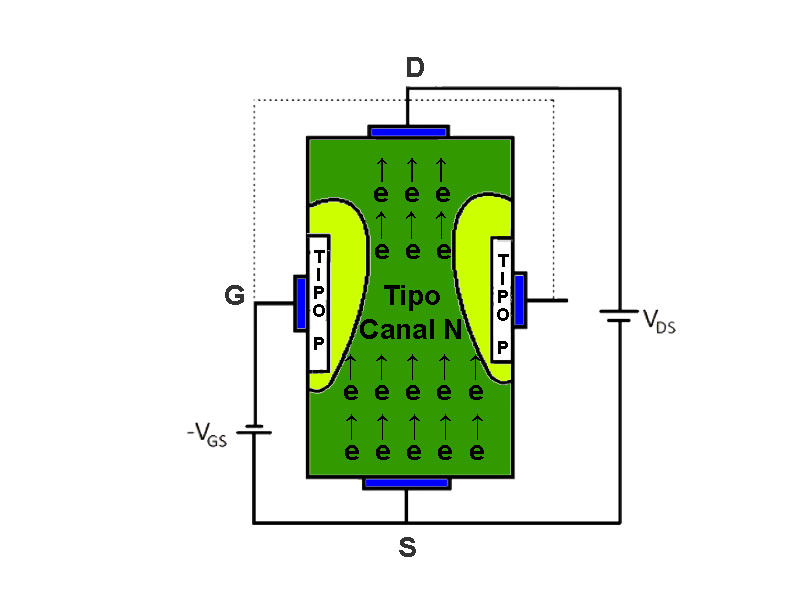
But when we apply a negative voltage across gate to source the depletion region is getting wider even if drain to source voltage is constant. By this way we can control the current flowing from drain to source.
As we see, the only difference in the symbol of a JFET N transistor and a P one is the direction of the arrow. Incoming for those with N channel and outgoing for those with P channel.
For typical operation, N-channel transistors are biased by applying a positive voltage between the drain and source (VDS), and a negative voltage between the gate and source (VGS). This allows current to flow in the direction of the drain towards the source. For P-channel JFETs, biasing requires a negative VDS voltage and a positive VGS voltage. This causes current to flow in the direction of the source towards the drain.
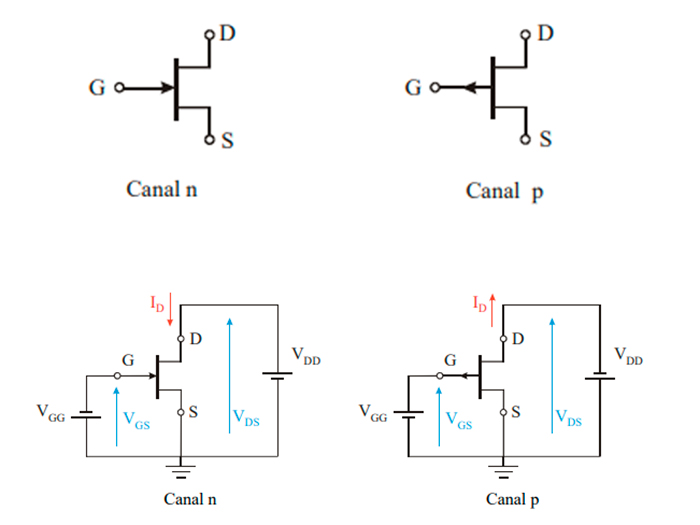
| CHANNEL N | CHANNEL P |
| VDS positive | VDS negative |
| VGS negative | VGS positive |
| ID positive (incoming) | ID negative (outgoing) |
If we now combine in the same graph the impact that both voltages (VDS and VGS) have on the operation of the device, we obtain what is known as the characteristic curves of the JFET transistor.
The output characteristic curves for an n-channel JFET are shown in the Figure below. In these curves, the drain current (ID) is represented as a function of the drain-source voltage (VDS) for different values of the gate-source voltage (VGS).
We note that the value of the VDS voltage for which the drain current enters saturation when VGS = 0 is sometimes represented as VP, referring to the "throttling" or "pinch-off" that occurs in the channel. It is important to note that this voltage VP can be considered of equal magnitude but with the opposite sign to the voltage VGSoff, a characteristic of the device.
On the other hand, for other values of VGS, the value of the VDS voltage at which saturation of the drain current is reached can be calculated using the expression VDSsat = VGS - VGSoff, where all voltages must be considered with their respective sign . That is, the more negative the VGS voltage, the sooner saturation will be reached, meaning that the channel will narrow for lower values of VDS, which makes sense since a more negative VGS means a smaller initial channel.
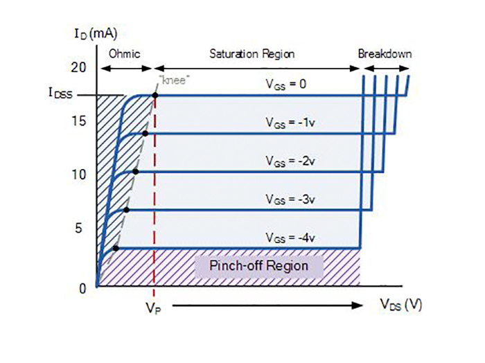
On this curve, we can identify four well-defined zones:
In this area of the graph, which corresponds to the horizontal axis, the current ID is equal to zero regardless of the value of VDS. This occurs when VGS values are less than or equal to VGSoff, indicating that the channel is completely closed.
This behavior occurs when the VDS values are less than the saturation values, that is, when VDS ≤ VGS - VGSoff. In this situation, the channel narrows mainly from the drain side, until reaching complete throttling in VDSsat. In this region, the transistor roughly resembles a variable resistor controlled by the gate voltage, especially for low values of VDS. As we approach VDSsat for each value of VGS, linearity is lost due to the narrowing of the channel approaching closure.
In this zone for VDS < VDSsat, the JFET behaves as a variable resistor with VGS.
This phase occurs when the VDS values are greater than VDSsat. Now, the current ID remains constant with changes in VDS (the long channel assumption being valid) and only depends on the applied voltage VGS. In this situation, the transistor functions as a current source controlled by the gate voltage, VGS.
The relationship between the applied voltage VGS and the current ID flowing through the channel in this phase is defined by the following equation:
| ID=IDSS (1- (VGS/vGSoff))2 |
For VDS > VDSsat, the JFET acts as a current source controlled by VGS.
When a p-n junction is reverse biased, the space charge zone increases. However, this reverse voltage has a limit, known as breakdown voltage, which is characteristic of each joint and is usually provided by the manufacturer in the specification sheets. If this breakdown voltage is exceeded, the joint is punctured, causing the device to rupture.


