


Stepper motors are direct current motors in which the rotation is divided into steps. They provide precise control, which is why they are used in printers, CNC controls, robotics, industry, etc.
What is a stepper motor or stepper motor?
A stepper motor, is a type of electric motor used to convert electrical pulses into discrete, precise movements. It is called "stepping" because the motor advances a certain number of individual steps in response to each electrical pulse it receives. These motors are widely used in applications that require precise positioning, such as 3D printers, CNC machines, robots, cameras, and other motion control systems.
The basic operation of a stepper motor is based on the interaction between a rotor (usually a series of permanent magnets) and a set of electromagnetic coils arranged around the rotor.
How does a stepper motor work?
A stepper motor is an electromechanical device that converts electrical pulses into discrete, precise mechanical movements. The components and detailed operation of a stepper motor are described below:
Basic components:
Stator: The stator is the fixed part of the motor and consists of a set of electromagnetic coils arranged around the rotor. These coils are the key to generating the movement of the motor.
Rotor: The rotor is the moving part of the motor and usually consists of a permanent magnet or a set of permanent magnets. The rotor is located in the center of the stator and can rotate in discrete steps.
Output shaft: The output shaft is the part of the rotor that is used to connect the motor to the load that is to be moved or positioned. Through the rotation of the rotor, the output shaft performs the desired mechanical work.
Operating principle:
- Coil Sequence: To move the rotor of a stepper motor, a specific set of electromagnetic coils in the stator must be activated sequentially. These coils are divided into groups and can be connected in different ways, depending on the type of stepper motor (unipolar or bipolar).
- Pulses: Electrical pulses are sent through the stator coils. Each electrical pulse activates a specific coil or group of coils for a short period of time. The direction and amount of movement depend on the activation sequence of the coils and how they are polarized.
- Stepping Motion: With each electrical pulse, the rotor of the stepper motor advances one step in the direction determined by the activation sequence of the coils. Each step represents a predefined angle, typically 1.8 degrees for 200 steps per revolution motors. Therefore, to rotate the rotor a full circle (360 degrees), 200 pulses are required.
- Position Control: Position control is achieved by sending the correct number of electrical pulses in the proper sequence. By controlling the number and direction of electrical pulses sent to the motor, the rotor and therefore the load connected to the output shaft can be precisely positioned.
- Summing up: So in this type of motor, we have a stationary stator and a rotor mounted on a shaft that rotates due to a magnetic field created by coils in the stator. When a coil is energized, an electromagnet is formed that attracts a magnet in the rotor, causing it to spin. By alternating between the coils, different steps of movement are achieved, including full steps, half steps, and microsteps. In short, the stepper motor works by magnetic attraction between the stator and rotor, allowing precise control of movement.
Working modes of a stepper motor
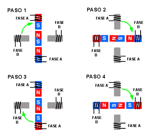
Stepper motor in full step mode
In this mode, the motor rotates at predefined angles, such as 1.8°, which means 200 steps are needed for a full rotation (200×1.8° = 360°). Shaft movement is achieved by energizing one or two coils. Using a single coil requires less power from the controller, while using two opposing coils increases motor power, speed and torque.
The figure below shows us how it works in full step mode with a 2-phase power supply:
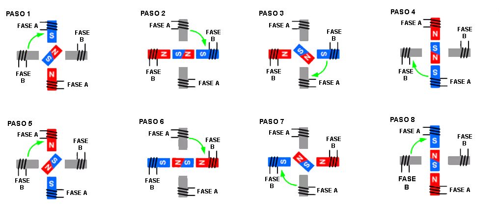
Stepper motor in half step mode
In half-step mode, the rotor stroke is divided by 2, meaning a single stroke is 0.9° instead of 1.8° in the example above. This results in 400 steps per complete revolution. In this mode, both motor coils receive power alternately, which increases the torque compared to single-phase mode operation. This also makes the motor run smoother and doubles the angular resolution.
The figure below shows the operation of the stepper motor in half step with a 2-phase power supply:
Stepper motor in microstep mode
The nominal pitch is divided into sections shorter than half a pitch, with a maximum division ratio of 256. The precise rotor positions are controlled by the magnetic flux generated by the coils fed by stepped waves. This mode is ideal for applications that require smooth operation and high precision.
However, when using microstepping, it is important to consider the speed requirements of the application. The inductive reactance of the coils increases with the switching frequency of the current in the motor, which can decrease the average current and, consequently, the motor torque. This can lead to problems such as oscillations, rotor stoppages or loss of steps in the driven machine. Therefore, it is crucial to consult the motor's specification sheet, which should include a graph showing the torque versus the frequency of current in the coils when using microstepping.
What type of stepper motor are there?
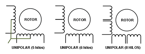
Unipolar stepper motors:
- Main features:
- In unipolar stepper motors, each coil has a current taking center (midpoint) and is connected to a switching transistor. They usually have 5, 6 or 8 output connection wires, depending on whether the midpoints of the two coils are united or independent.
- They are easier to control compared to bipolar motors due to their coil arrangement and the possibility of using unipolar transistors.
- They generally have less torque and efficiency compared to bipolar motors, making them more suitable for low-load, low-power applications.
- In unipolar stepper motors, each coil has a current taking center (midpoint) and is connected to a switching transistor. They usually have 5, 6 or 8 output connection wires, depending on whether the midpoints of the two coils are united or independent.
- Functioning:
- In a unipolar stepper motor, the coils are activated sequentially in a fixed pattern to make the rotor advance in discrete steps.
- To turn the motor in one direction, the coils are energized in a specific order (usually one coil is activated at a time), and to rotate it in the opposite direction, the order of activation of the coils is reversed.
- Each coil is connected through a unipolar transistor that is turned on and off to turn current through the coil on or off, creating a magnetic field that pushes or pulls on the rotor.
- Advantages of unipolar stepper motors:
-
- Ease of control: They are easier to control due to the arrangement of the coils and the availability of unipolar transistors.
- Fewer components: They require fewer electronic components for control, which can reduce the cost and complexity of control circuits.
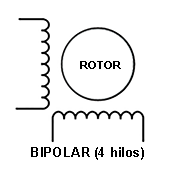
Bipolar stepper motors:
- Main features:
- In bipolar stepper motors, there is no current taking center in each coil, and the coils are connected directly or via H-bridges to reverse the direction of the current.
- They generally offer better performance in terms of torque and efficiency compared to unipolar motors.
They require more complex control circuits due to the need to reverse the direction of current in the coils.
- Functioning:
- Bipolar stepper motors are activated by reversing the polarity of the current in the coils rather than turning individual coils on or off.
- To rotate the motor in one direction, current is applied in one direction through the coils, and to rotate it in the opposite direction, the direction of current is reversed.
- H-bridges or similar control circuits are required to change the direction of current in the coils.
- Advantages of bipolar stepper motors:
- Greater Torque: They have greater available torque compared to unipolar motors, making them more suitable for heavy-duty applications.
- Higher Efficiency: They tend to be more energy efficient due to the lack of resistance in the coils caused by the center of the outlet.
- Better overall performance: They are ideal for applications that require precise movements and strength.
In summary, the choice between a unipolar and a bipolar stepper motor depends on the specific requirements of the application. Unipolar motors are simpler to control and are suitable for low-load, low-power applications, while bipolar motors offer higher performance in terms of torque and efficiency, making them ideal for heavy-load, high-precision applications. although they require more complex control circuits
How to connect a stepper motor?
This will depend on the type of engine we have and the type of operating mode we want to make the engine work. In general we will use stepper motor drivers that incorporate H bridges, and do not raise connection questions and depending on the connection mode varies. The article is too extensive for the purpose of this article and we will only explain the cases of connection with an H bridge or bipolar mode, as it is the most common.
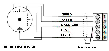
Bipolar or 4-wire stepper motor
The connection of these motors is the simplest. We have the same number of cables or wires as in the controller or motor driver. Only the motor casing has been shielded from ground to avoid possible interference.
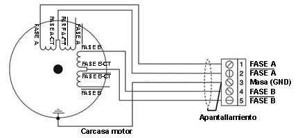
6-wire stepper motor
In this case we have a unipolar stepper motor, which is the same as the previous bipolar one to which a medium tap has been added to each winding of the motor. In this case we can connect in the following ways:
- Bipolar full coil: Many of these motors do not require the use of these central taps and can also be connected as in the case of the previous figure.
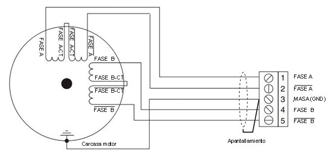
- Bipolar half coil: In this case the motor torque is greatly reduced, so we will need additional voltages to be able to reach the required torque, which could overheat our motor. In this sense, it is advisable to read the engine manufacturer's specifications. In any case the connection would be the following:
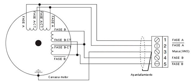
5-wire stepper motor
This type of stepper motor is a unipolar type with 2 windings in which the two middle taps of each winding are linked internally. We would connect the ends of the coils to the outputs of the driver or H-bridge, leaving the common coils unconnected.
8-wire stepper motor
In some motors, the manufacturer opts for a 4-winding design with 8 cables, which allows us to put the windings in series or in parallel, depending on whether the speed or torque of the motor is more important.
- Wiring an 8-wire stepper motor as a bipolar motor (series windings)
- Wiring an 8-wire stepper motor as a bipolar motor (windings in parallel)
Common Stepper Motor Sizes
Stepper motors are available in a variety of sizes and standard configurations to suit various applications. Standard sizes are defined primarily by their mounting size, which is measured in millimeters or inches, and their torque capacity. Below are some of the common standard sizes of stepper motors:
NEMA 17: This is one of the most common and widely used sizes. NEMA 17 stepper motors have a square flange with a mounting dimension of 1.7 x 1.7 inches (43.18 x 43.18 mm) and are used in a variety of applications, from 3D printers to medium-sized CNC machines.
NEMA 23: NEMA 23 stepper motors have a larger square flange with a mounting dimension of 2.3 x 2.3 inches (58.42 x 58.42 mm). These motors are suitable for applications requiring higher torque and are used in larger CNC machines, industrial printers and automation equipment.
NEMA 34: NEMA 34 stepper motors have an even larger square flange with a mounting dimension of 3.4 x 3.4 inches (86.36 x 86.36 mm). They are high torque motors used in heavy industrial applications, such as cutting machinery and loading equipment.
NEMA 11: These motors are smaller than NEMA 17, with a mounting dimension of approximately 1.1 x 1.1 inches (28 x 28 mm). They are used in applications where space is limited and moderate torque is needed.
NEMA 14: NEMA 14 stepper motors are even smaller, with a mounting dimension of around 1.4 x 1.4 inches (35 x 35 mm). They are ideal for compact and lightweight applications.
NEMA 08: These are the smallest motors with a mounting dimension of approximately 0.8 x 0.8 inches (20 x 20 mm). They are used in micro and miniaturized applications.
There are times that any of the previous models are also marketed with a spindle mounted as the rotor shaft. On this shaft there is a threaded support that rotates with the revolutions of the motor. So together we have a linear actuator of excellent precision. View linear actuator based on stepper motor
Please note that within each standard size, stepper motors can vary in terms of length, rated torque, rated current, and other specifications. Choosing the size and type of stepper motor will depend on the specific requirements of your application, such as the load to be moved, the precision needed, and the space available.
