


A clamp meter is an electrical device that is capable of measuring the electric current that passes through a cable without the need for contact.
Introduction to clamp meters
Clamps are devised to enhance the current measuring capabilities of various instruments such as digital multimeters, power instruments, oscilloscopes, handheld scopes, recorders or loggers, among others. The clamp meters are positioned around the current-carrying conductor to conduct non-contact current measurements without disrupting the circuit under test. These clamps output current or voltage signals directly proportional to the measured current, thereby furnishing current measuring and displaying capabilities to instruments with low current or voltage inputs.
During measurements, the circuit of the current-carrying conductor remains unbroken, ensuring electrical isolation from the instrument's input terminals. Consequently, the instrument's low input terminal may be either floated or earthed. Interruption of the power supply is unnecessary when employing a current clamp for measurements, thus mitigating costly downtime.
True RMS measurements within the clamp's frequency response are achievable by utilizing most Chauvin-Arnoux current clamps with a true RMS multimeter. In many instances, RMS measurements are constrained not by the clamps but by the connected instrument. Optimal results are delivered by clamps featuring inherent high accuracy, good frequency response, and minimal phase shift.
Several Chauvin Arnoux® clamps are patented for their unique circuitry and design.
AC CURRENT CLAMPS
• Theory of Operation:
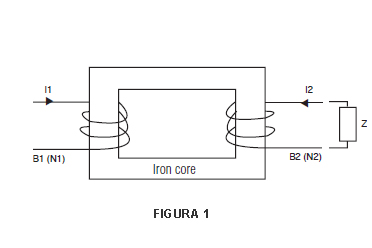
An AC current clamp may be viewed as a variant of a simple current transformer. A transformer (figure 1) consists essentially of two coils wound around a shared iron core. A current, I1, is passed through coil B1, inducing a current, I2, in coil B2 through the common core. The number of turns in each coil and the current are linked by the equation:
N1 x I1 = N2 x I2, where N1 and N2 represent the number of turns in each coil. From this equation, we can derive that: I2 = N1 x I1/N2 or I1 = N2 x I2/N1.
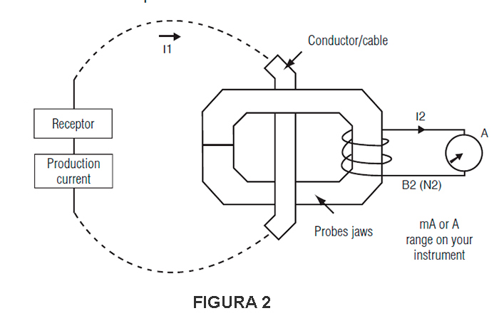
This principle is similarly applied to a current clamp (figure 2). The articulated magnetic core houses coil B2 and attaches to a conductor through which current, I1, is flowing. B1 represents the conductor where the user measures the current, with the number of turns, N1, set to one. The current sensor clamped around the conductor delivers an output proportional to the number of turns in its coil, B2, according to the equation:
I2 (clamp output) = N1/N2 x I1, where N1 = 1 or clamp output = I1/N2 (number of turns in the clamp's coil).
Measuring I1 directly is frequently challenging due to currents that are either too high to be directly fed into a meter or because accessing the circuit is impractical. To ensure a manageable output level, a predetermined number of turns are wound around the coil of the clamp.
The number of turns in the winding of the clamp typically consists of a whole number, such as 100, 500, or 1,000. If N2 equals 1,000, then the clamp has a ratio of N1/N2, or 1/1,000, expressed as 1,000:1. Another representation of this ratio is that the clamp output is 1 mA/A, meaning that for every 1 A flowing in the jaw window, the clamp output is 1 mA (I2). Various other ratios are feasible, such as 500:5, 2,000:2, 3,000:1, 3,000:5, etc., catering to different applications.
The most prevalent application involves using a current clamp in conjunction with a digital multimeter. For instance, consider a current clamp with a ratio of 1,000:1 (model C100), yielding an output of 1 mA/A. This implies that any current passing through the probe jaws will generate a corresponding output current:
| Conductor input | Clamp output |
| 1000A | 1A |
| 750A | 750mA |
| 250A | 250mA |
| 10A | 10mA |
The output of the clamp is linked to a DMM configured for the AC current range to process the clamp output. Subsequently, to ascertain the current in the conductor, the DMM reading is multiplied by the ratio. For example, a reading of 150 mA on a DMM set to a 200 mA range signifies 150 mA x 1000 = 150 A in the measured conductor.
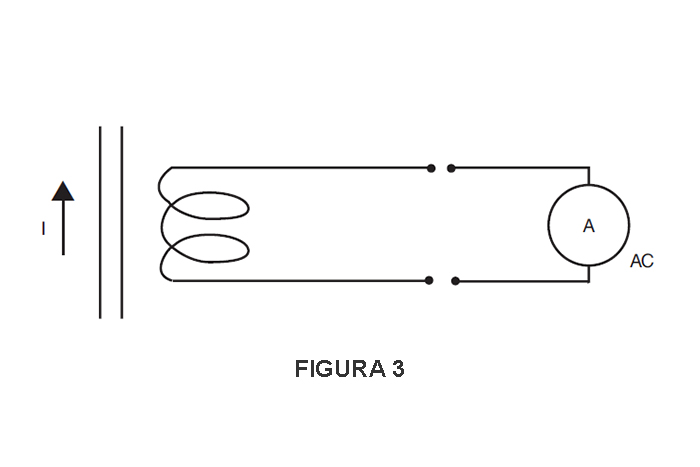
Current clamps are compatible with other instruments featuring current ranges, provided these instruments possess the necessary input impedance (see figure 3).
Current clamps may also feature AC or DC voltage outputs to facilitate current measurements with instruments (such as loggers, scopes, etc.) that exclusively offer voltage ranges (see figures 4 and 5).
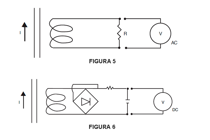
This is achieved simply by conditioning the output of the current clamp within the clamp itself to provide voltage.
• Principle of Operation
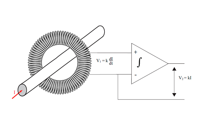
The AmpFlex® and MiniFlex® sensors operate based on the Rogowski coil principle. The primary circuit consists of the conductor carrying the alternating current to be measured, while the secondary circuit comprises a unique coil wound on a flexible support. This coil generates a voltage at its terminals that is proportional to the derivative of the primary current being measured.
u = μ0.n/(2πr) S di/dt
Where μ0 = vacuum permeability, S = surface area of a turn, n = number of turns and r = core radius.
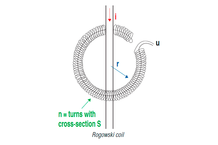
This alternating current voltage u is then transmitted through a shielded cable to the casing containing all the processing electronics and the battery power supply. Because there are no magnetic circuits on these sensors, they are very lightweight and flexible. Without magnetic circuits, there is no saturation effect or overheating. This feature ensures excellent linearity and low phase shift.
AC/DC CLAMP-ON CURRENT PROBES
• Theory of Operation (Hall effect)
In contrast to traditional AC transformers, AC/DC current measurement often relies on detecting the intensity of a magnetic field generated by a current-carrying conductor using the Hall-effect principle in a semiconductor chip. When a thin semiconductor material (as shown in figure 6) is positioned perpendicular to a magnetic field (B), and an electrical current (Id) flows through it, a voltage (Vh) is generated across the semiconductor. This voltage is referred to as the Hall voltage, named after the American scientist Edwin Hall, who first observed this phenomenon.
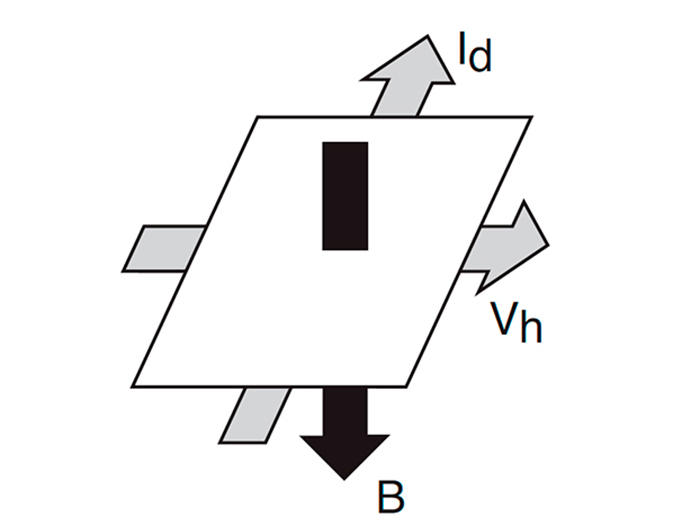
When the Hall device drive current (Id) remains constant, the magnetic field (B) becomes directly proportional to the current in a conductor. Consequently, the Hall output voltage (Vh) serves as a representation of that current.
Such an arrangement brings about two significant advantages for universal current measurement. Firstly, because the Hall voltage is independent of a reversing magnetic field and solely reliant on its strength, the device can be employed for DC measurement. Secondly, as the magnetic field strength fluctuates due to varying current flow in the conductor, the device exhibits an instantaneous response to change.
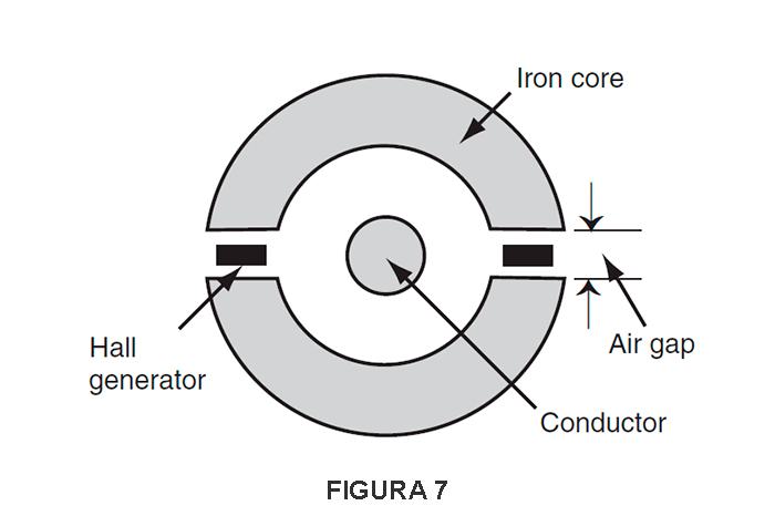
As a result, complex AC waveforms can be detected and measured with high precision and minimal phase shift. The fundamental construction of a clamp jaw assembly is depicted in Figure 7 (note: depending on the type of current clamp, one or two Hall generators are utilized).
The AC/DC ammeter clamps from Chauvin Arnoux have been developed using the aforementioned principle, along with patented electronic circuits incorporating signal conditioning for linear output and temperature compensation. These clamps offer a wide dynamic range and frequency response, providing high-precision linear output for use in all areas of current measurement, up to 1,500 A. Additionally, they can measure direct currents without the need for expensive and energy-consuming shunts, as well as alternating currents of several kHz with precision to meet the requirements of complex signals and RMS measurements.
The clamp outputs are in mV (mV DC when measuring direct current and mV AC when measuring alternating current) and can be connected to most instruments with a voltage input, such as digital multimeters, recorders, oscilloscopes, portable oscilloscopes, recorders, etc. Furthermore, Chauvin Arnoux offers various technologies for direct current measurements, such as in the K1 and K2, designed to measure very low direct currents using saturated magnetic circuit technology.
The AC/DC clamps also offer the opportunity to display or measure true effective values in alternating current or alternating current plus direct current.
AC OR DC CURRENT MEASUREMENT
• Connect the clamp to the instrument
• Select the function and range
• Clamp the clamp around a single conductor
• Read the conductor’s current value
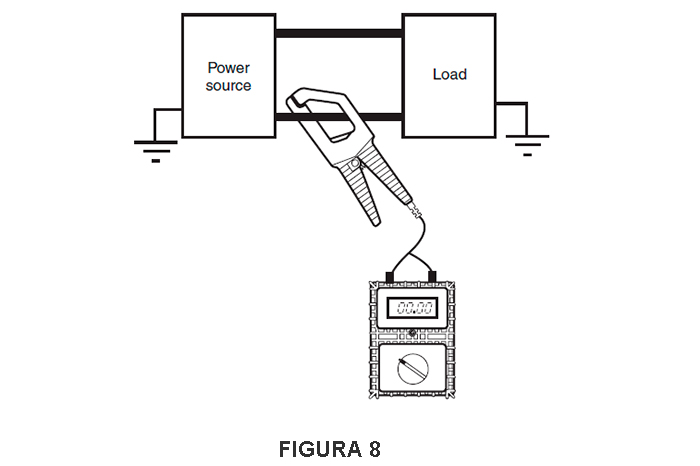
Examples (figure 8):
- AC: clamp model: Y2N
Ratio: 1000:1
Output: 1 mA AC/A AC
DMM: set to 200 mA AC range
DMM reading: 125 mA AC
Current in conductor:
125 mA x 1000 = 125 A AC
- DC: clamp model: PAC 21
1 mV DC/A DC (Hall sensor)
DMM: set to 200 mV DC range
DMM reading: 160 mV DC
Current in conductor: 160 A DC
- AC: clamp model: PAC 11
Output: 1 mV AC/A AC
(Hall sensor)
DMM: set to 200 mV AC range
DMM reading: 120 mV AC
Current in conductor: 120 A AC
- DC: micro clamp K1
Output: 1 mV/mA
DMM: set to 200 mV DC range
DMM reading: 7.4 mV DC
Current in conductor: 7.4 mA
Measurements of Low Currents, Process Loops and Leakage Currents
Multiple clamps are available for low current measurements. For instance, models K1 and K2 offer a 50 mA DC sensitivity, with model K2 suitable for 4-20 mA process loops.
Example: 4-20 mA loop
Clamp model: K2
Output: 10 µV/mA
DMM set to 200 mV DC range
DMM reading: 135 mV DC
Loop current: 13.5 mA DC
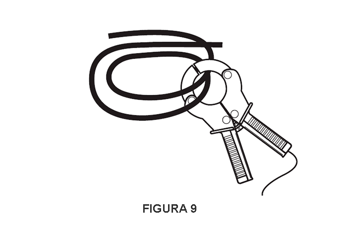
When the current being measured is too low for the clamp or greater accuracy is required, it's feasible to pass the conductor through the probe jaws multiple times. The current value is then determined by the ratio of the reading to the number of turns.
Example: Figure 9
Clamp model: C100
Ratio: 1000:1
DMM set to 200 mA AC range
Turns in clamp jaw: 10
DMM reading: 60 mA AC
Current in conductor: 60 mA x 1,000 / 10 = 6,000 mA = 6 A
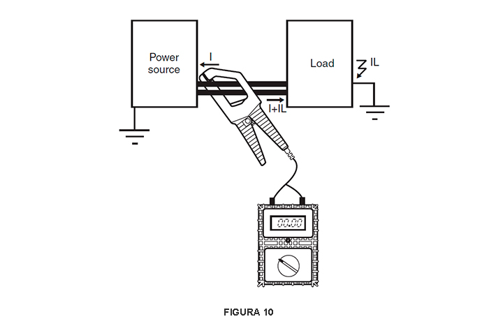
When the clamp is placed around two conductors with different polarities, the resulting reading will be the difference between the two currents. If the currents are the same, the reading will be zero (Figure 10). When a reading other than zero is obtained, it indicates the amount of leakage current on the load.
To measure low currents or leakage, you require a clamp that can accurately measure low values, such as the B102 or C173 models. However, earth leakage currents can also be directly measured using a basic model (Figure 11).
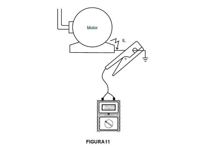
Example: Figure 11
MINI 05
Ratio: 1 mV AC/mA AC
DMM set to 200 mA AC range
DMM reading: 10 mV AC
Leakage current: 10 mA AC
Selecting a current probe
To choose the right current probe for your needs, consider the following questions:
- Determine whether you are measuring AC or DC current (DC current clamps are often categorized as AC/DC because they can measure both types).
- Identify the maximum and minimum current levels you'll be measuring. Ensure that the clamp's accuracy at lower levels is suitable, or opt for a low-current measurement clamp. Keep in mind that many clamps offer better accuracy at higher current levels. Some clamps are specifically designed for very low DC or AC currents.
- Consider the size of the conductor you'll be clamping onto. This will determine the size of the clamp jaws you need.
- Decide what type of clamp output you require or can work with (e.g., mA, mV, AC, DC, etc.). Check the maximum receiver impedance to ensure that the clamp will perform according to your specifications.
Other factors you may want to consider include:
- What is the working voltage of the conductor to be measured? Ensure not to use current clamps that do not support the voltage being measured.
- What type of termination is needed: connectors, banana-type cables, or BNC?
- Will the probe be used for measuring harmonics or for power measurement?
- Check the frequency specifications and phase shift specifications.
- When using current clamps for frequency measurement or high-frequency signals, the bandwidth of the amperometric clamp should be considered.
