Available
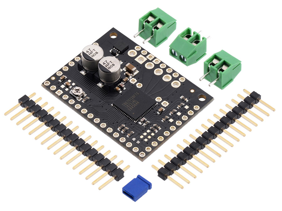
This breakout board makes it easy to use Toshiba’s TB67S128FTG microstepping bipolar stepper motor driver, which features adjustable current limiting and microstepping down to 1/128-step. In addition, it has the ability to dynamically select an optimal decay mode by monitoring the actual motor current, and it can automatically reduce the driving current below the full amount when the motor is lightly loaded to minimize power consumption and heat generation. The driver has a wide operating voltage range of 6.5 V to 44 V and can deliver approximately 2.1 A per phase continuously without a heat sink or forced air flow (up to 5 A peak). It features built-in protection against under-voltage, over-current, and over-temperature conditions; our carrier board also adds reverse-voltage protection (up to 40 V).
This product is a carrier board or breakout board for Toshiba’s TB67S128FTG stepper motor driver; we therefore recommend careful reading of the TB67S128FTG datasheet (2MB pdf) before using this product. This stepper motor driver offers microstep resolutions down to 1/128 of a step, and it lets you control one bipolar stepper motor at up to approximately 2.1 A per phase continuously (5 A peak) without a heat sink or forced air flow (see the Power Dissipation Considerations section below for more information.) The board breaks out every control pin and output of the TB67S128FTG, making all of the driver’s features available to the user.
Here are some of the board’s key features:
Two interface modes to select from:
Clock mode for simple step and direction control
Serial mode for controlling the driver’s many features through a serial interface (this mode also allows for serial control of the current limit)
Eight different step modes: full-step, half-step, 1/4-step, 1/8-step, 1/16-step, 1/32-step, 1/64-step, and 1/128-step
Adjustable current control lets you set the maximum current output with a potentiometer, which lets you use voltages above your stepper motor’s rated voltage to achieve higher step rates
Four different decay modes: mixed decay (two timing ratios), fast decay, or Advanced Dynamic Mixed Decay (ADMD), which dynamically switches between slow and fast decay modes by monitoring the state of current decay (not according to fixed timing)
Configurable Active Gain Control (AGC) automatically reduces drive current to minimize power consumption and heat generation when maximum torque is not needed
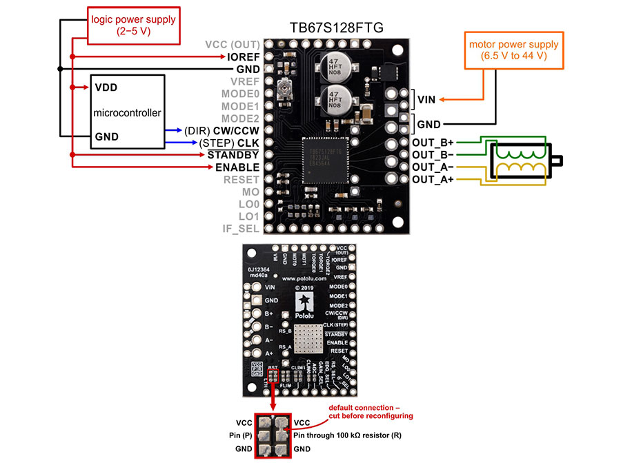
Motor supply voltage: 6.5 V to 44 V
Can deliver up to approximately 2.1 A per phase continuously (5 A peak) without additional cooling
Can interface directly with 3.3 V and 5 V systems
Protection against over-current/short-circuit and over-temperature
Open-load detection
Active-low error outputs indicate over-current, over-temperature, or open-load condition
Carrier board adds reverse-voltage protection up to 40 V
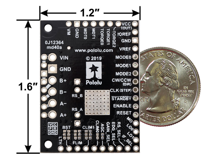
Carrier board breaks out all of the TB67S128FTG pins in a compact size (1.2″ × 1.6″)
Exposed solderable ground pad below the driver IC on the bottom of the PCB
Motor driver: TB67S128FTG
Minimum operating voltage: 6.5 V
Maximum operating voltage: 44 V
Continuous current per phase: 2.1 A
Maximum current per phase: 5.0 A
Minimum logic voltage: 2 V2
Maximum logic voltage: 5.5 V
Microstep resolutions: full, 1/2, 1/4, 1/8, 1/16, 1/32, 1/64, 1/128
Current limit control: potentiometer, digital, SPI-programmable