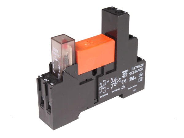
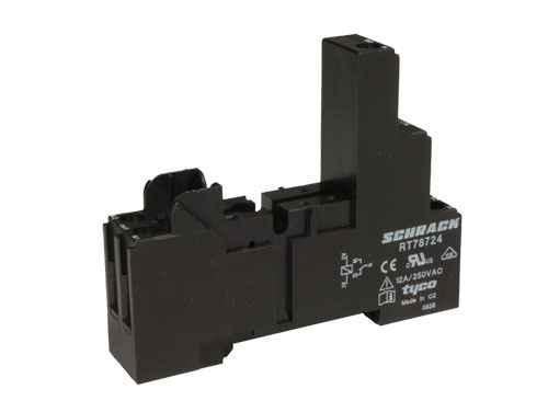
DIN rail socket and other accessories are optional
 Available
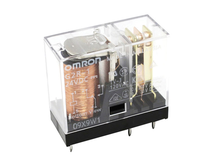
The Omron G2R-1 24VDC is a general-purpose monostable electromechanical power relay with a 24 V DC coil and one changeover contact in an SPDT (1 CO) arrangement. It has five straight pins and can be mounted directly on a printed circuit board (PCB) or inserted into a compatible socket.
For control-panel installations it can, for example, be used with a compatible DIN-rail socket for 1-contact relays, allowing the wiring to remain on the socket and the relay to be replaced without desoldering.
The 24 V DC coil has a rated current of 21.8 mA and an approximate power consumption of 0.53 W. Coil resistance is 1 100 Ω at 23 °C with a tolerance of ±10 %. The must-operate voltage is no more than 70 % of rated voltage and the must-release voltage is at least 15 %. At 23 °C, the specified maximum coil voltage is 170 % of rated voltage; this is the maximum within a varying operating voltage range and is not a continuous voltage rating.
Switching capacity depends on load type. With a resistive load, the contact is rated at 10 A at 250 V AC or 10 A at 30 V DC. With an inductive load, the ratings are 7.5 A at 250 V AC with cos φ = 0.4 and 5 A at 30 V DC with L/R = 7 ms. The 10 A figure must therefore not be interpreted as a rating that applies indiscriminately to every type of load.
The contacts use a cadmium-free silver alloy. The relay provides 5 kV AC dielectric strength between the coil and contacts and a minimum insulation resistance of 1 000 MΩ. The insulation distance between coil and contacts is 8 mm clearance and 8 mm creepage. It can operate from −40 °C to 70 °C and the DC-coil version has a minimum mechanical endurance of 20 000 000 operations.
| Brand | Omron |
| Model | G2R-1 24VDC |
| Electrónica Embajadores code | RL3A814 |
| Series | G2R |
| Type | General-purpose electromechanical power relay |
| Relay function | Monostable |
| Contact configuration | SPDT, 1 CO (1 changeover contact) |
| Number of poles | 1 |
| Number of pins | 5 |
| Terminal type | Straight pins |
| Mounting | Direct PCB mounting or compatible socket, including DIN-rail sockets |
| Enclosure protection | Flux protected |
| Contact material | Cadmium-free silver alloy |
| Coil polarity | Non-polarised |
| Rated coil voltage | 24 V DC |
| Rated coil current | 21.8 mA |
| Coil resistance | 1 100 Ω at 23 °C, ±10 % |
| Coil power consumption | Approximately 0.53 W |
| Must-operate voltage | ≤ 70 % of rated voltage |
| Must-release voltage | ≥ 15 % of rated voltage |
| Maximum coil voltage | 170 % of rated voltage at 23 °C; maximum within a varying operating voltage range, not a continuous rating |
| Rated resistive load | 10 A at 250 V AC; 10 A at 30 V DC |
| Rated inductive load | 7.5 A at 250 V AC (cos φ = 0.4); 5 A at 30 V DC (L/R = 7 ms) |
| Rated carry current | 10 A |
| Maximum switching current | 10 A |
| Maximum switching voltage | 380 V AC; 125 V DC |
| Maximum switching power, resistive load | 2 500 VA; 300 W |
| Maximum switching power, inductive load | 1 875 VA; 150 W |
| Contact resistance | ≤ 30 mΩ, initial value |
| Operate time | ≤ 15 ms |
| Release time | ≤ 5 ms, DC coil |
| Insulation resistance | ≥ 1 000 MΩ at 500 V DC, initial value |
| Dielectric strength, coil to contacts | 5 kV AC, 50/60 Hz, for 1 min |
| Dielectric strength between contacts | 1 kV AC, 50/60 Hz, for 1 min |
| Insulation distance, coil to contacts | 8 mm clearance; 8 mm creepage |
| Mechanical endurance | ≥ 20 000 000 operations, DC coil, at 18 000 operations/h |
| Electrical endurance | ≥ 100 000 operations, at 1 800 operations/h under rated load |
| Operating temperature | −40–70 °C, with no icing |
| Operating humidity | 5 %–85 % |
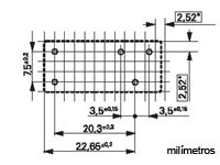
| Maximum dimensions | 29 × 13 × 25.5 mm |
| Weight | Approximately 17 g |
| Compliance | RoHS |